Build - Pedal Project: Iss. 1 Fuzz with Classic Wiring


The Iss. 1 PCB can be built in a variety of ways ranging from completely custom builds to meticulously reproduced versions of the original Fuzz Face. This guide covers the original wiring and parts selections with only minor changes to allow for battery disconnect switching with common 1/4" jacks. Otherwise the parts shown match the original NKT275 version of this pedal. Some other variations exist but this is the most common build from Arbiter England.
We have several versions of the Iss. 1 board available. P-PC-FUZZ-ISS1-X is a modern version of the board available in multiple colors whereas P-PC-FUZZ-ISS1-BRN is made of a phenolic board material like originals.
This diagram shows the Iss. 1 Fuzz build in an original Fuzz Face style enclosure but it can be built the same way in any enclosure. The P-H1590P1 is a common choice for vintage style fuzz builds but the Iss. 1 board can fit into smaller pedals like the 1590BB and others.
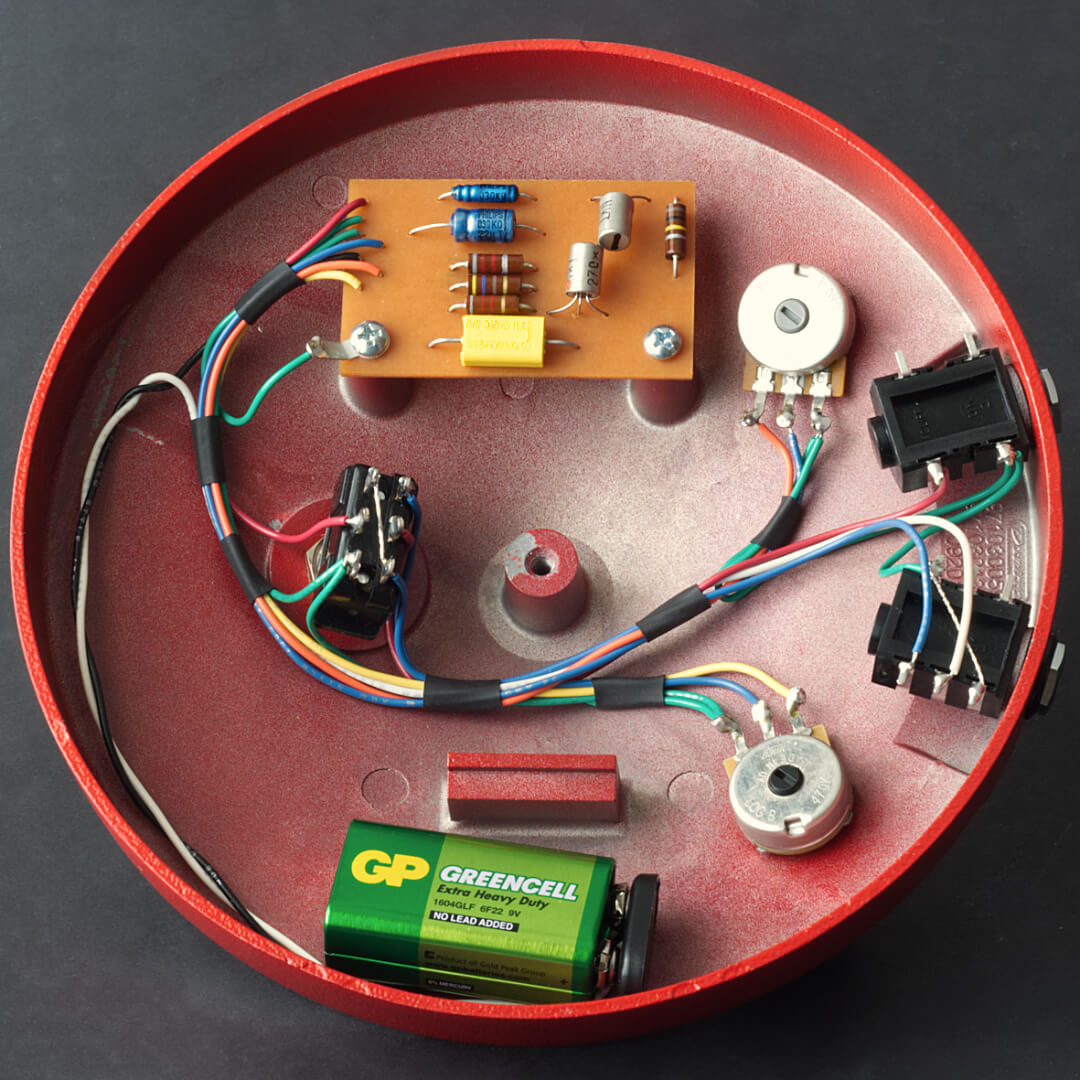
Figure 1: Iss. 1 Vintage Wiring Layout

The resistors used in originals are 1/2W carbon composition resistors. The two most important values are going to be the 33kΩ which sets the bias for Q1 and the 8.2kΩ resistor which sets the Q2 bias. Depending on the transistors used, one or both of these values may need to be adjusted for proper functionality. The 33kΩ resistor influences the bias of both transistors, so adjusting this value first is recommended. Alternatively, with proper transistor selection, the stock values can be used. Our full selection of 1/2W carbon composition resistors can be found here.
The original 2.5µF and 20µF electrolytic capacitor values are fairly uncommon these days especially in the smaller sizes needed for this build. The 2.5µF capacitor is most often replaced with a 2.2µF capacitor but a 2µF will work just as well here.
For the 20µF capacitor the most common sub is a 22µF but a 25µF will work well too.
The square yellow capacitor on the original pedals is a .01µF polycarbonate film capacitor. This material is no longer produced, but the unique features it provides are not utilized in the Fuzz Face, so most film types such as polyester or polypropylene will work just as well. Our full selection of .01µF film capacitors can be found here.
The germanium PNP transistors in the original Fuzz Face are the NKT275. Originals are nearly impossible to source so people have substituted all sorts of germanium transistors in this pedal.
The two ways to approach this are:
- to try a variety of transistors until a good balance is found. This can be difficult or impossible if your batch is far from the specs found in the NKT275.
- replacing the resistors on the collectors as mentioned above. These are the 33kΩ which sets the bias for Q1 and the 8.2kΩ resistor which sets the Q2 bias.
It is best to build the pedal on a breadboard and substitute transistors or resistors until it biases correctly before committing parts to the final build. Many people use a trimmer in place of one or both of the 33kΩ and 8.2kΩ resistors to further simplify the process. A bias voltage of -0.7VDC on the collector of Q1 and -4.5VDC on the collector of Q2 is the optimal bias settings for the germanium Fuzz Face, but many people like to deviate from these values especially since originals rarely landed exactly on those voltages. Starting off at those two voltages and then adjusting to taste is a great way to approach this.
Our full selection of PNP germanium transistors can be found here.
Figure 2: Iss. 1 Vintage Wiring Schematic

The basic hardware includes a switched mono and switched stereo jack. Cliff makes a variety of jacks that are perfect for these. The original value of the fuzz control is a B1K pot but many builders prefer a C1K pot to balance the sweep. An A500K pot is used for the volume control. A switched pot such as the R-VA24S-500KA can be a good mod for a battery disconnect which is nice when using the build on a pedalboard. A DPDT footswitch is used on the original pedal but a 3PDT footswitch is required if adding an LED. The classic build uses a battery clip only but a charge pump pcb such as P-PC-INV-SCREW or P-PC-INV-SWITCH can allow use with a standard 9V power supply.